Calibrating Your Camera
Important
In order to detect AprilTags and use 3D mode, your camera must be calibrated at the desired resolution! Inaccurate calibration will lead to poor performance.
To calibrate a camera, images of a ChArUco board (or chessboard) are taken. By comparing where the grid corners should be in object space (for example, a corner once every inch in an 8x6 grid) with where they appear in the camera image, we can find a least-squares estimate for intrinsic camera properties like focal lengths, center point, and distortion coefficients. For more on camera calibration, please review the OpenCV documentation.
Warning
PhotonVision supports many resolution configuration options, with only a minimum of 640x480 required. However, higher resolutions may be too performance-intensive for some coprocessors to handle. Therefore, we recommend experimenting to see what works best for your coprocessor.
Note
The calibration data collected during calibration is specific to each physical camera, as well as each individual resolution.
Calibration Tips
Warning
The usage of chessboards can result in bad calibration results if multiple similar images are taken. We strongly recommend that teams use ChArUco boards instead!
Accurate camera calibration is required in order to get accurate pose measurements when using AprilTags and 3D mode. The tips below should help ensure success:
Ensure the images you take have the target in different positions and angles, with as big of a difference between angles as possible. It is important to make sure the target overlay still lines up with the board while doing this. Tilt no more than 45 degrees.
Use as big of a calibration target as your printer can print.
Ensure that your printed pattern has enough white border around it.
Ensure your camera stays in one position during the duration of the calibration.
Make sure you get all 12 images from varying distances and angles.
Take at least one image that covers the total image area, and generally ensure that you get even coverage of the lens with your image set.
Have good lighting, having a diffusely lit target would be best (light specifically shining on the target without shadows).
Ensure the calibration target is completely flat and does not bend or fold in any way. It should be mounted/taped down to something flat and then used for calibration, do not just hold it up.
Avoid having targets that are parallel to the lens of the camera / straight on towards the camera as much as possible. You want angles and variations within your calibration images.
Following the ideas above should help in getting an accurate calibration.
Calibrating using PhotonVision
2. Print out the calibration target.
In the Camera Calibration tab, we’ll print out the calibration target using the “Download” button. This should be printed on 8.5x11 printer paper. This page shows using an 8x8 ChArUco board (or chessboard depending on the selected calibration type).
Warning
Ensure that there is no scaling applied during printing (it should be at 100%) and that the PDF is printed as is on regular printer paper. Check the square size with calipers or an accurate measuring device after printing to ensure squares are sized properly, and enter the true size of the square in the UI text box. For optimal results, various resources are available online to calibrate your specific printer if needed.
3. Select calibration resolution and fill in appropriate target data.
We’ll next select a resolution to calibrate and populate our pattern spacing, marker size, and board size. The provided chessboard and ChArUco board are an 8x8 grid of 1 inch square. The provided ChArUco board uses the 4x4 dictionary with a marker size of 0.75 inches (this board does not need the old OpenCV pattern selector selected). Printers are not perfect, and you need to measure your calibration target and enter the correct marker size (size of the ArUco marker) and pattern spacing (aka size of the black square) using calipers or similar. Finally, once our entered data is correct, we’ll click “start calibration.”
Warning
Old OpenCV Pattern selector. This should be used in the case that the calibration image is generated from a version of OpenCV before version 4.6.0. This would include targets created by calib.io. If this selector is not set correctly the calibration will be completely invalid. For more info view this GitHub issue.
Note
If you have a calib.io ChArUco Target you will have to enter the paramaters of your target. For example if your target says “9x12 | Checker Size: 30 mm | Marker Size: 22 mm | Dictionary: ArUco DICT 5x5”, you would have to set the board type to Dict_5x5_1000, the pattern spacing to 1.1811 in (30 mm converted to inches), the marker size 0.866142 in (22 mm converted to inches), the board width to 12 and the board height to 9. If you chose the wrong tag family the board wont be detected during calibration. If you swap the width and height your calibration will have a very high error.
4. Take at calibration images from various angles.
Now, we’ll capture images of our board from various angles. It’s important to check that the board overlay matches the board in your image. The further the overdrawn points are from the true position of the chessboard corners, the less accurate the final calibration will be. We’ll want to capture enough images to cover the whole camera’s FOV (with a minimum of 12). Once we’ve got our images, we’ll click “Finish calibration” and wait for the calibration process to complete. If all goes well, the mean error and FOVs will be shown in the table on the right. The FOV should be close to the camera’s specified FOV (usually found in a datasheet) usually within + or - 10 degrees. The mean error should also be low, usually less than 1 pixel.
Accessing Calibration Images
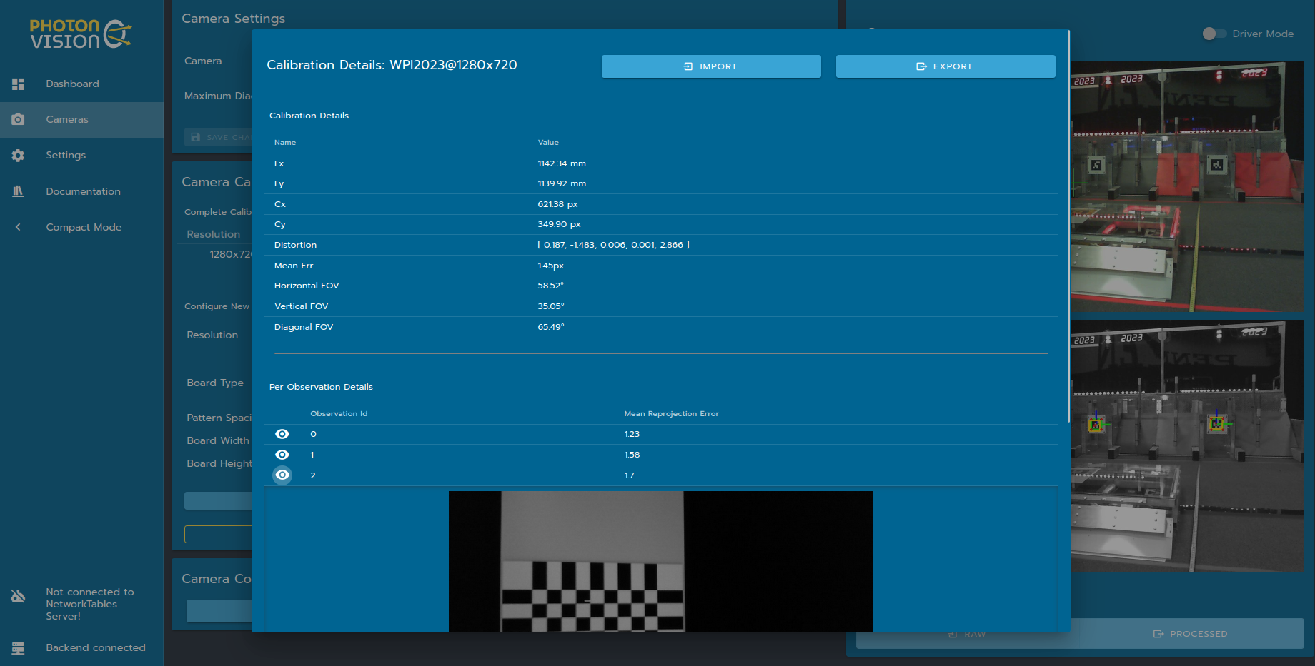
Details about a particular calibration can be viewed by clicking on that resolution in the calibrations tab. This tab allows you to download raw calibration data, upload a previous calibration, and inspect details about calculated camera intrinsic.
Note
More info on what these parameters mean can be found in OpenCV’s docs
Fx/Fy: Estimated camera focal length, in pixels
Fx/Cy: Estimated camera optical center, in pixels. This should be at about the center of the image
Distortion: OpenCV camera model distortion coefficients
FOV: calculated using estimated focal length and image size. Useful for gut-checking calibration results
Mean Err: Mean reprojection error, or distance between expected and observed chessboard cameras for the full calibration dataset
Below these outputs are the snapshots collected for calibration, along with a per-snapshot mean reprojection error. A snapshot with a larger reprojection error might indicate a bad snapshot, due to effects such as motion blur or misidentified chessboard corners.
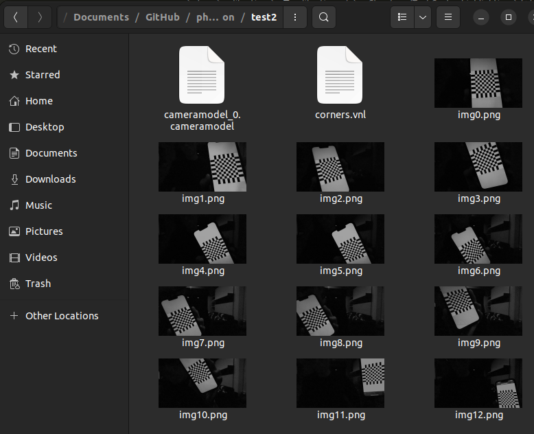
Calibration images can also be extracted from the downloaded JSON file using this Python script. This script will unpack calibration images, and also generate a VNL file for use with mrcal.
python3 /path/to/calibrationUtils.py path/to/photon_calibration.json /path/to/output/folder
Investigating Calibration Data with mrcal
mrcal is a command-line tool for camera calibration and visualization. PhotonVision has the option to use the mrcal backend during camera calibration to estimate intrinsics. mrcal can also be used post-calibration to inspect snapshots and provide feedback. These steps will closely follow the mrcal tour – I’m aggregating commands and notes here, but the mrcal documentation is much more thorough.
Start by Installing mrcal. Note that while mrcal calibration using PhotonVision is supported on all platforms, but investigation right now only works on Linux. Some users have also reported luck using WSL 2 on Windows as well. You may also need to install feedgnuplot. On Ubuntu systems, these commands should be run from a standalone terminal and not the one built into vscode.
Let’s run calibrationUtils.py as described above, and then cd into the output folder. From here, you can follow the mrcal tour, just replacing the VNL filename and camera imager size as necessary. My camera calibration was at 1280x720, so I’ve set the XY limits to that below.
$ cd /path/to/output/folder
$ ls
matt@photonvision:~/Documents/Downloads/2024-01-02_lifecam_1280$ ls
  corners.vnl  img0.png  img10.png  img11.png  img12.png  img13.png  img1.png
  img2.png  img3.png  img4.png  img5.png  img6.png  img7.png  img8.png
  img9.png  cameramodel_0.cameramodel

$ < corners.vnl       \
  vnl-filter -p x,y | \
  feedgnuplot --domain --square --set 'xrange [0:1280] noextend' --set 'yrange [720:0] noextend'

As you can see, we didn’t do a fantastic job of covering our whole camera sensor – there’s a big gap across the whole right side, for example. We also only have 14 calibration images. We’ve also got our “cameramodel” file, which can be used by mrcal to display additional debug info.
Let’s inspect our reprojection error residuals. We expect their magnitudes and directions to be random – if there’s patterns in the colors shown, then our calibration probably doesn’t fully explain our physical camera sensor.
$ mrcal-show-residuals --magnitudes --set 'cbrange [0:1.5]' ./camera-0.cameramodel
$ mrcal-show-residuals --directions --unset key ./camera-0.cameramodel


Clearly we don’t have anywhere near enough data to draw any meaningful conclusions (yet). But for fun, let’s dig into camera uncertainty estimation. This diagram shows how expected projection error changes due to noise in calibration inputs. Lower projection error across a larger area of the sensor imply a better calibration that more fully covers the whole sensor. For my calibration data, you can tell the projection error isolines (lines of constant expected projection error) are skewed to the left, following my dataset (which was also skewed left).
$ mrcal-show-projection-uncertainty --unset key ./cameramodel_0.cameramodel
